So after a little over a year of working with only manual dials, I thought it was time to join the digital age. Dials are fine, it's good to know that I can do it...but it's such a huge waste of time. I'd rather be making chips than counting on my fingers.
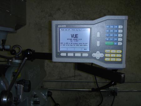
After A LOT of searching and research I decided I was comfortable with the price/quality/features of the Accurite VUE two axis system. I got it brand new on Ebay...for less than you can get it anywhere else...which is still pretty pricey.
Just to prevent too much suspense from building, I like the system a lot and I'm glad I purchased it. However, it has a lot of fancy features that I still need to learn how to use. I goes way beyond bolt patterns.
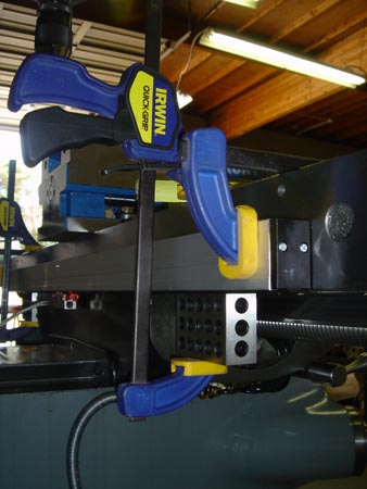
Anyway, the instructions call for no more than .020 deviation from end to end on the scale mounting. The table was easy to line up using a couple of clamps and 123 blocks.
Of course one of the harder challenges is locating, drilling and tapping the mounting holes "perfectly."
I don't have anything fancy like a magnetic drill press to make life easy so I got a little creative.
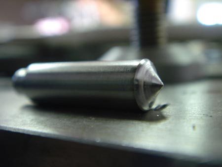
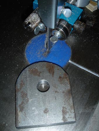
This is a 1/4" dowel pin turned into a transfer punch. Oh yeah, I don't have a transfer punch set either.
I just wanted to note...turning dowel pins is not easy. They are already hard and work harden like crazy. Thanks carbide insert tooling.
So this is my makeshift transfer punch. I don't know that there would be room to swing a hammer even if I had a full length transfer punch so this worked out nicely.
Sine the DRO install I've had occasion to use these buggers a few more times and they work great.
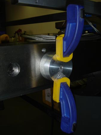
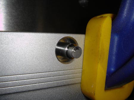
Great, marked all of the holes and removed the scale. I turned a little drill guide with a wide flange so I could clamp it. Using an air drill I made quick work of these holes.
If you have air, I'm a HUGE fan of air drills for holes under 1/4" diameter. The light weight, good maneuverability and high RPM beat the pants off an electric drill any day. Make one 1/4" hole with an air drill and you'll wonder why you didn't get one sooner.
I made a similar tapping guide block. Worked great and all the holes lined up fine. Unfortunately I forgot to take pictures of mounting the scale to the side of the knee but it was basically the same procedure.
The only difference is, the side of the knee is not a precision surface like the back of the table. So, I had to put a 1/4" washer between the back of the scale and the knee, because there was a slight bow in the middle. One washer at each end allowed the scale to clear the bow and mount up straight.
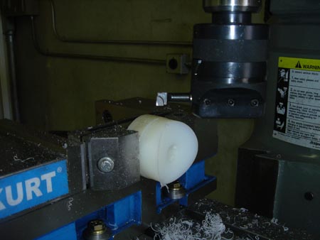
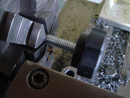
I didn't take a picture but I think I stole this trick from Frank. How do you accurately set a diameter on the boring head? I set the vise jaws to the desired diameter (opening width) using calipers. Then you drop the spindle and the boring head down, so the tool is inside the vise jaws. Rotate the boring head 180 degrees and adjust it out till it just touches on both sides of the jaws. I looked for the link on Frank's site but couldn't find it.
Anyway, I set the head and put a radius on this sucker.
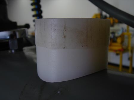
Look Ma! It fits!
I actually made it "slightly" underside so that when I tighten down the bolt the nylon will compress and make a really snug fit.
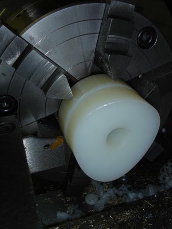
Parting nylon. Fun!
Did I mention how much I love my band saw?
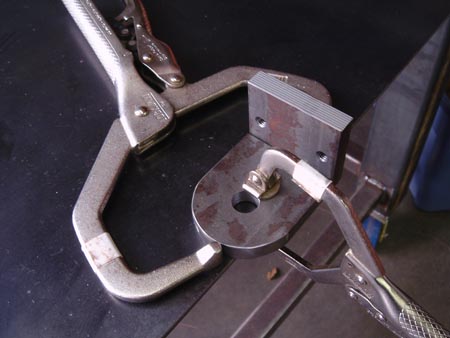
Clamp it. Weld it. Pretty standard really.
Is this making sense yet? All mounted up and with the first piece of the mounting arm bracket installed.
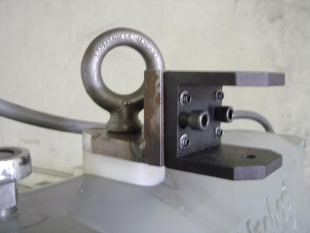
This is probably a good time to point out I screwed up. Well, I couldn't see the future is what I mean. I should NOT have rounded the horizontal part of the mounting bracket...even though it looks nice.
In retrospect, I should have left it square so I could weld on a bracket that would also hold my dental light! It will remain mounted to my cart I guess, but it would have been sweet to mount this on the left side of this bracket.
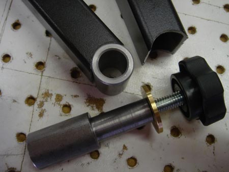
I'm forgetting to take pictures again. The original mounting arm was one piece. I didn't like that so I cut it in half. I used a hole saw to cut the fish mouths and turned a little joint out of CRS.
Then I welded the joint pieces to the arms.
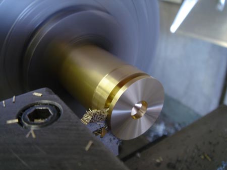
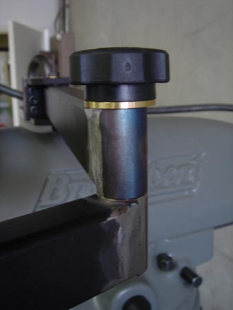
I always like brass bushings...so I made one.
The knob was a little to long so I took care of that.
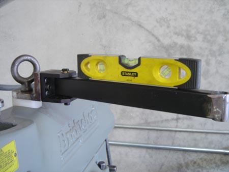
Now I have the arm leveled and the joint welded up and ground.
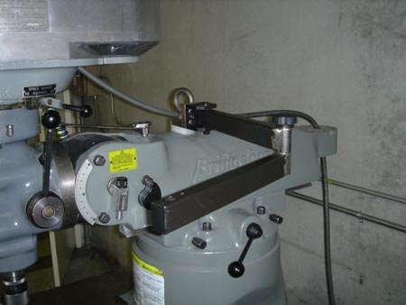
Here is the second segment installed.
A close up.
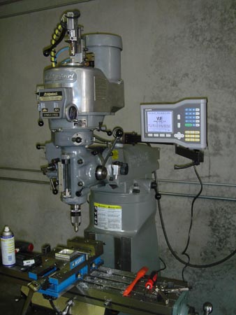
And finally mounted! I was concerned that it might not be rigid enough to take my tippy tapping on the keypad but it's very solid.
The two piece arms gives me better positioning control and also drops the whole unit down about two inches which is marginally more comfortable.
Well, there ya go. I guess you can tell I have a problem with constantly modifying and upgrading things. Oh well.